M-LAG 实验
实验拓扑
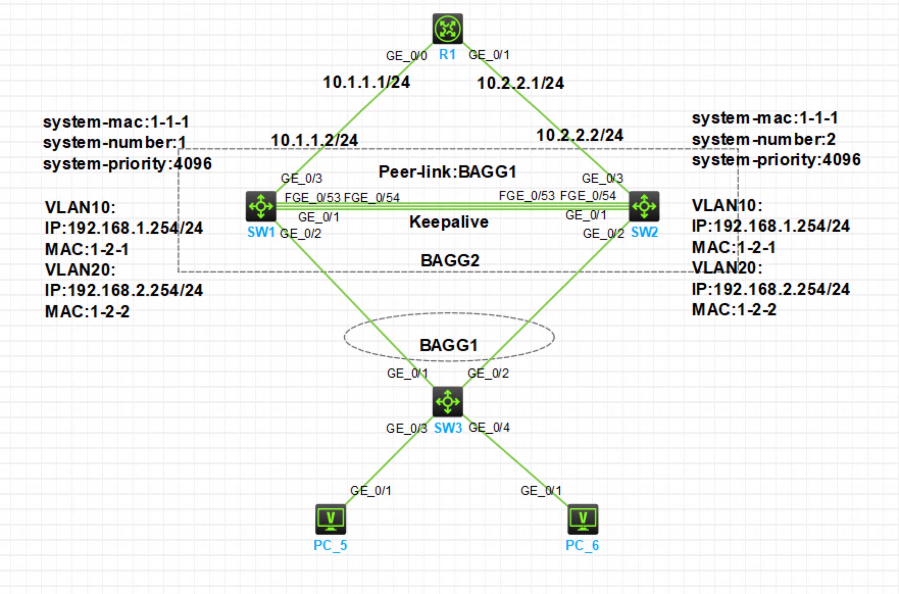
注:如无特别说明,描述中的 R1 或 SW1 对应拓扑中设备名称末尾数字为 1 的设备,R2 或 SW2 对应拓扑中设备名称末尾数字为 2 的设备,以此类推;此实验需要在模拟器中使用交换机型号 S6850
实验需求
- SW3 为接入交换机,连接 PC5 在 VLAN 10,连接 PC6 在 VLAN 20,SW3 双上行连接到两台核心交换机
- SW1 和 SW2 为核心交换机,配置 M-LAG,并作为 VLAN 10 和 VLAN 20 的三层网关,下行跨设备聚合对接接入交换机 SW3。上行不配置 M-LAG,分别通过两条链路接入到路由器 R1
实验解法
在 SW3 上创建 VLAN 10 和 VLAN 20,连接 PC5 和 PC6 的接口分别以 Access 类型接入到 VLAN 10 和 VLAN 20,步骤略
为 PC 配置 IP 地址和网关,步骤略
配置 SW1 和 SW2 形成 M-LAG 系统
步骤 1:修改 SW1 系统 MAC 地址为 1-1-1,系统编号为 1,优先级 4096
[SW1]m-lag system-mac 1-1-1
[SW1]m-lag system-number 1
[SW1]m-lag system-priority 4096
步骤 2:在 SW1 上配置 G1/0/1 口为 Keepalive 接口,Keepalive 源地址为本端 1.1.1.1,目的地址为 SW2 的 1.1.1.2,并在 MAD 中排除 Keepalive 接口
[SW1]m-lag keepalive ip destination 1.1.1.2 source 1.1.1.1
[SW1]interface g1/0/1
[SW1-GigabitEthernet1/0/1]port link-mode route
[SW1-GigabitEthernet1/0/1]ip address 1.1.1.1 24   //Keepalive 接口 IP 地址可自定义网络中未使用的地址,双方 Keepalive 口地址需要在同一网段
[SW1]m-lag mad exclude interface g1/0/1
步骤 3:在 SW1 上把 F1/0/53 和 F1/0/54 口加入到 BAGG1 动态聚合口,并把该聚合口配置为 SW1 的 Peer-link 口
[SW1]interface Bridge-Aggregation 1
[SW1-Bridge-Aggregation1]link-aggregation mode dynamic
[SW1]interface range f1/0/53 to f1/0/54
[SW1-if-range]port link-aggregation group 1
[SW1]interface Bridge-Aggregation 1
[SW1-Bridge-Aggregation1]port m-lag peer-link 1
步骤 4:修改 SW2 系统 MAC 地址与 SW1 相同为 1-1-1,系统编号为 2,优先级 4096
[SW2]m-lag system-mac 1-1-1
[SW2]m-lag system-number 2
[SW2]m-lag system-priority 4096
步骤 5:在 SW2 上配置 G1/0/1 口为 Keepalive 接口,Keepalive 源地址为本端 1.1.1.2,目的地址为 SW1 的 1.1.1.1,并在 MAD 中排除 Keepalive 接口
[SW2]m-lag keepalive ip destination 1.1.1.1 source 1.1.1.2
[SW2]interface g1/0/1
[SW2-GigabitEthernet1/0/1]port link-mode route
[SW2-GigabitEthernet1/0/1]ip address 1.1.1.2 24
[SW2]m-lag mad exclude interface g1/0/1
步骤 6:在 SW2 上把 F1/0/53 和 F1/0/54 口加入到 BAGG1 动态聚合口,并把该聚合口配置为 SW2 的 Peer-link 口
[SW2]interface Bridge-Aggregation 1
[SW2-Bridge-Aggregation1]link-aggregation mode dynamic
[SW2]interface range f1/0/53 to f1/0/54
[SW2-if-range]port link-aggregation group 1
[SW2]interface Bridge-Aggregation 1
[SW2-Bridge-Aggregation1]port m-lag peer-link 1
步骤 7:此时在 SW1 和 SW2 上可以查看到 M-LAG 系统已经建立
[SW1]display m-lag summary
Flags: A -- Aggregate interface down, B -- No peer M-LAG interface configured
        C -- Configuration consistency check failed

Peer-link interface: BAGG1
Peer-link interface state (cause): UP
Keepalive link state (cause): UP
在 SW1 和 SW2 上配置下连 SW3 的接口为 M-LAG 接口,实现跨设备聚合
步骤 1:在 SW1 上创建 BAGG2 动态聚合口,把连接 SW3 的接口加入该聚合口,并设置为 M-LAG 接口
[SW1]interface Bridge-Aggregation 2
[SW1-Bridge-Aggregation1]link-aggregation mode dynamic
[SW1]interface g1/0/2
[SW1-if-range]port link-aggregation group 2
[SW1]interface Bridge-Aggregation 2
[SW1-Bridge-Aggregation1]port m-lag group 1
步骤 2:在 SW2 上创建 BAGG2 动态聚合口,把连接 SW3 的接口加入该聚合口,并设置为 M-LAG 接口
[SW2]interface Bridge-Aggregation 2
[SW2-Bridge-Aggregation1]link-aggregation mode dynamic
[SW2]interface g1/0/2
[SW2-if-range]port link-aggregation group 2
[SW2]interface Bridge-Aggregation 2
[SW2-Bridge-Aggregation1]port m-lag group 1
步骤 3:在 SW3 上创建 BAGG1 动态聚合口,把连接 SW1 和 SW2 的接口加入该聚合口
[SW3]interface Bridge-Aggregation 1
[SW3-Bridge-Aggregation1]link-aggregation mode dynamic
[SW3]interface range g1/0/1 to g1/0/2
[SW3-if-range]port link-aggregation group 1
步骤 4:此时在 SW1,SW2 和 SW3 上可以查看到跨设备链路聚合已经正常工作
[SW1]display link-aggregation summary
AGG        AGG   Partner ID              Selected  Unselected  Individual  Share
Interface  Mode                          Ports     Ports       Ports       Type
--------------------------------------------------------------------------------
BAGG1      D     0x8000, aa7f-9f6a-0200  2         0           0           Shar
BAGG2      D     0x8000, aa7f-a318-0300  1         0           0           Shar
[SW3]display link-aggregation summary AGG AGG Partner ID Selected Unselected Individual Share Interface Mode Ports Ports Ports Type -------------------------------------------------------------------------------- BAGG1 D 0x1000, 0001-0001-0001 2 0 0 Shar在 SW1 和 SW2 上为 VLAN 10 和 VLAN 20 创建三层接口,两端配置相同的 MAC 地址和 IP 地址
步骤 1:在 SW1 和 SW2 上创建 VLAN 10 和 VLAN 20,把 SW1、SW2 和 SW3 之间相连的聚合口配置为 Trunk,并允许 VLAN 10 和 VLAN 20 通过,步骤略
步骤 2:在 SW1 上创建 VLAN 10 和 VLAN 20 的三层接口,配置 MAC 地址和 IP 地址
[SW1]interface vlan 10
[SW1-Vlan-interface10]mac-address 1-2-1
[SW1-Vlan-interface10]ip address 192.168.1.254 24
[SW1]interface vlan 20
[SW1-Vlan-interface20]mac-address 1-2-2
[SW1-Vlan-interface20]ip address 192.168.2.254 24
步骤 2:在 SW2 上创建 VLAN 10 和 VLAN 20 的三层接口,配置与 SW1 相同的 MAC 地址和 IP 地址
[SW2]interface vlan 10
[SW2-Vlan-interface10]mac-address 1-2-1
[SW2-Vlan-interface10]ip address 192.168.1.254 24
[SW2]interface vlan 20
[SW2-Vlan-interface20]mac-address 1-2-2
[SW2-Vlan-interface20]ip address 192.168.2.254 24
在 SW1 和 SW2 上配置上行接口 IP 地址,配置 R1 的 IP 地址,步骤略
在 SW1、SW2 和 R1 上配置 OSPF,使路由互通
效果测试:在 PC 上测试能 Ping 通网关和 R1
<H3C>ping 192.168.1.254
Ping 192.168.1.254 (192.168.1.254): 56 data bytes, press CTRL_C to break
56 bytes from 192.168.1.254: icmp_seq=0 ttl=255 time=1.000 ms
56 bytes from 192.168.1.254: icmp_seq=1 ttl=255 time=1.000 ms
56 bytes from 192.168.1.254: icmp_seq=2 ttl=255 time=1.000 ms
56 bytes from 192.168.1.254: icmp_seq=3 ttl=255 time=0.000 ms
56 bytes from 192.168.1.254: icmp_seq=4 ttl=255 time=1.000 ms
<H3C>ping 10.1.1.1 Ping 10.1.1.1 (10.1.1.1): 56 data bytes, press CTRL_C to break 56 bytes from 10.1.1.1: icmp_seq=0 ttl=254 time=2.000 ms 56 bytes from 10.1.1.1: icmp_seq=1 ttl=254 time=1.000 ms 56 bytes from 10.1.1.1: icmp_seq=2 ttl=254 time=1.000 ms 56 bytes from 10.1.1.1: icmp_seq=3 ttl=254 time=1.000 ms 56 bytes from 10.1.1.1: icmp_seq=4 ttl=254 time=1.000 ms