三层交换实验
实验拓扑
注:如无特别说明,描述中的 R1 或 SW1 对应拓扑中设备名称末尾数字为 1 的设备,R2 或 SW2 对应拓扑中设备名称末尾数字为 2 的设备,以此类推
实验需求
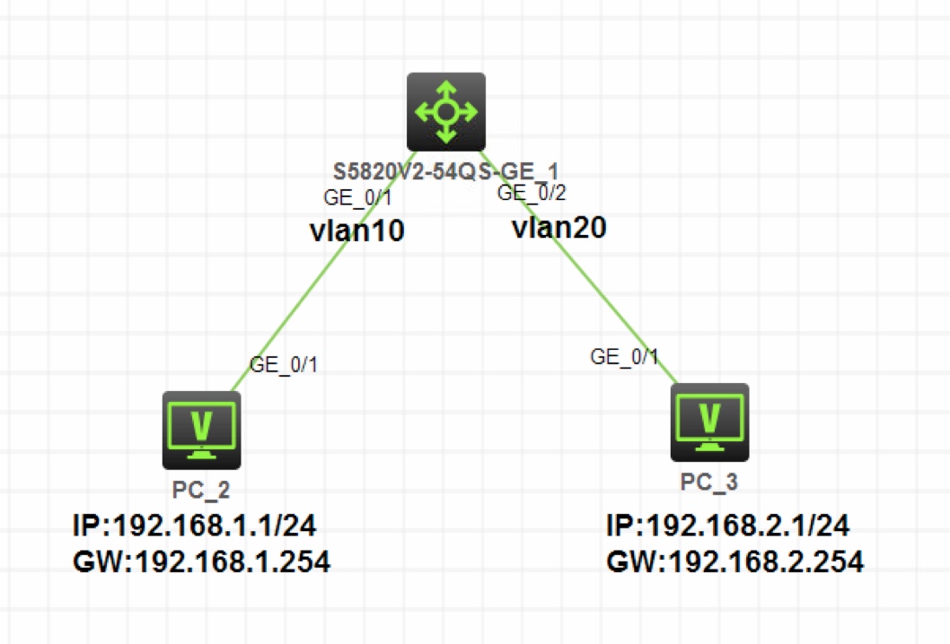
- 按照图示为 PC2 和 PC3 配置 IP 地址和网关
- PC2 属于 Vlan10,PC3 属于 Vlan20,在三层交换机上配置 Vlanif 三层接口实现 Vlan10 和 Vlan20 三层互通
- PC2 和 PC3 可以互通
实验解法
- PC 配置 IP 地址部分略
PC2 属于 Vlan10,PC3 属于 Vlan20,在三层交换机上配置 Vlanif 三层接口实现 Vlan10 和 Vlan20 三层互通
分析:在三层交换机上实现 Vlan 间的路由互通,只需要对每个 Vlan 开启 Vlanif 三层接口,并配置对应网段的网关地址就可以了
步骤 1:在 SW1 上创建 Vlan10 和 Vlan20,并把 g1/0/1 接口加入 Vlan10,把 g1/0/2 接口加入 Vlan20
[SW1]vlan 10
[SW1-vlan10]port g1/0/1
[SW1-vlan10]vlan 20
[SW1-vlan20]port g1/0/2
步骤 2:在 SW1 上对 Vlan10 和 Vlan20 开启 Vlanif 接口,并配置 Vlanif10 接口 IP 地址为 Vlan10 的网关地址
192.168.1.254/24,配置 Vlanif20 接口 IP 地址为 Vlan20 的网关地址192.168.2.254/24[SW1]interface Vlan-interface 10 [SW1-Vlan-interface10]ip address 192.168.1.254 24[SW1]interface Vlan-interface 20 [SW1-Vlan-interface20]ip address 192.168.2.254 24分析:配置结束后,在 SW1 上查看路由表,会发现已经产生了到达
192.168.1.0/24网段和192.168.2.0/24网段的直连路由,出接口分别指向各自 Vlanif 接口,证明 SW1 已经可以对 Vlan10 和 Vlan20 间的数据进行三层转发了[SW1]display ip routing-table Destinations : 16 Routes : 16 Destination/Mask Proto Pre Cost NextHop Interface …… 192.168.1.0/24 Direct 0 0 192.168.1.254 Vlan10 …… 192.168.2.0/24 Direct 0 0 192.168.2.254 Vlan20测试在 PC3 上 Ping PC4 ,可以 Ping 通 PC4
<H3C>ping 192.168.2.1
Ping 192.168.2.1 (192.168.2.1): 56 data bytes, press CTRL_C to break
56 bytes from 192.168.2.1: icmp_seq=0 ttl=254 time=36.000 ms
56 bytes from 192.168.2.1: icmp_seq=1 ttl=254 time=25.000 ms
56 bytes from 192.168.2.1: icmp_seq=2 ttl=254 time=27.000 ms
56 bytes from 192.168.2.1: icmp_seq=3 ttl=254 time=29.000 ms
56 bytes from 192.168.2.1: icmp_seq=4 ttl=254 time=39.000 ms