RRPP 实验
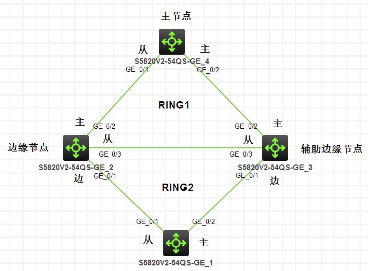
实验拓扑
注:如无特别说明,描述中的 R1 或 SW1 对应拓扑中设备名称末尾数字为 1 的设备,R2 或 SW2 对应拓扑中设备名称末尾数字为 2 的设备,以此类推;另外,同一网段中,IP 地址的主机位为其设备编号,如 R3 的 g0/0 接口若在
192.168.1.0/24网段,则其 IP 地址为192.168.1.3/24,以此类推
实验需求
- 网络中所有交换机之间的链路配置为 Trunk,放行所有 VLAN
- 按照图示配置 RRPP 保护所有 VLAN 数据,Ring1 为主环,Ring2 为子环,其他节点和主从端口如图,控制 VLAN 为 Vlan100
实验解法
网络中所有交换机之间的链路配置为 Trunk,放行所有 VLAN,步骤略
把所有交换机的相关端口都禁用 stp,步骤略
配置 RRPP
步骤 1:在 SW4 上配置为 RRPP 主节点,保护 Instance0-32,控制VLAN 为 Vlan100,运行在 Ring1,为主环,G1/0/2 口为主端口,G1/0/1 口为副端口
[SW4]rrpp domain 1
[SW4-rrpp-domain1]protected-vlan reference-instance 0 to 32
[SW4-rrpp-domain1]control-vlan 100
[SW4-rrpp-domain1]ring 1 node-mode master primary-port g1/0/2 secondary-port g1/0/1 level 0
[SW4-rrpp-domain1]ring 1 enable
[SW4]rrpp enable
步骤 2:在 SW3 上配置为 RRPP Ring1 中的传输节点,和 Ring2 中的辅助边缘节点
[SW3]rrpp domain 1
[SW3-rrpp-domain1]protected-vlan reference-instance 0 to 32
[SW3-rrpp-domain1]control-vlan 100
[SW3-rrpp-domain1]ring 1 node-mode transit primary-port g1/0/2 secondary-port g1/0/3 level 0
[SW3-rrpp-domain1]ring 2 node-mode assistant-edge edge-port g1/0/1
[SW3-rrpp-domain1]ring 1 enable
[SW3-rrpp-domain1]ring 2 enable
[SW3]rrpp enable
步骤 3:在 SW2 上配置为 RRPP Ring1 中的传输节点,和 Ring2 中的边缘节点
[SW2]rrpp domain 1
[SW2-rrpp-domain1]protected-vlan reference-instance 0 to 32
[SW2-rrpp-domain1]control-vlan 100
[SW2-rrpp-domain1]ring 1 node-mode transit primary-port g1/0/2 secondary-port g1/0/3 level 0
[SW2-rrpp-domain1]ring 2 node-mode edge edge-port g1/0/1
[SW2-rrpp-domain1]ring 1 enable
[SW2-rrpp-domain1]ring 2 enable
[SW2]rrpp enable
步骤 4:在 SW1 上配置为 RRPP Ring2 的主节点
[SW1]Rrpp domain 1
[SW1-rrpp-domain1]protected-vlan reference-instance 0 to 32
[SW1-rrpp-domain1]control-vlan 4092
[SW1-rrpp-domain1]ring 2 node-mode master primary-port g1/0/2 secondary-port g1/0/1 level 1
[SW1-rrpp-domain1]ring 2 enable
[SW1]rrpp enable